 |
| April 19, 2016 | Volume 12 Issue 15 |
Designfax weekly eMagazine

Archives
Partners
Manufacturing Center
Product Spotlight
Modern Applications News
Metalworking Ideas For
Today's Job Shops
Tooling and Production
Strategies for large
metalworking plants
Wheels: What are you smoking?
Automating short-circuit testing for automotive systems and harness design
By Mike Stamper, Mentor Graphics
Protecting vehicle wire harnesses from overloads that could be catastrophic is a critical design criterion. The designer must ensure that the fusing strategy protects the wiring. This process typically involves calculating the maximum load on each wire manually and then comparing the result to a spreadsheet that may have been created many years ago.
This article describes a method of determining the exact amount of current a wire can carry without damaging the insulation. These values can then be used to automate fusing strategy, ensuring proper protection of all circuits.
INTRODUCTION
The current way that most companies test designs is often based on long-obsolete assumptions, excess caution, and a tendency not to "fix what isn't broken." In addition, this process is very error prone due to its manual nature. You might find that alarming -- and it is -- but cars and planes are driving and flying just fine. There are several reasons that is so. First, most circuits are over protected. Due to the manual nature of most design processes, designers tend to err on the side of caution; this means wires that are larger than needed for the actual load. Over protection adds both cost and weight to the harness.
Next, these in-place processes are based on physical testing. Very expensive physical prototypes are built, and test engineers physically test the design to ensure the circuits are protected. This is costly both in time and money, and is often so late in the design process that changes resulting from this testing are very expensive to make.
And, let's face it, engineers and designers are smart. Many designs are simply carried over from year to year. History tells them what works and what doesn't -- but we must ask the question: Is this the most efficient way to design?
ANALYSIS AND SIMULATION
Simulation is a common term in automotive electrical and electronic systems. Unfortunately, it's seldom implemented, and if so, often creates bottlenecks. A highly trained skilled simulation expert must create complex models, run their simulations, and then analyze the results. Then the results are fed back to the harness engineering team who then, in turn, must make decisions based on the often-complex and difficult-to-understand graphs and results.
An important input that is always missing in doing simulation this way is the actual configuration of the vehicle. Not all loads are present in all vehicles. An example is a car where navigation is optional. Which simulation will be done -- with navigation or without? Let's add an optional moonroof into the mix: Now you have 22 = 4 vehicle models to simulate. As you add in more optional content, you can see the number of simulation combinations climbs to 2n, where n = the number of options.
For a simulation and modeling expert who has expertise in the creation of motor models and wire models, the complexity of potentially billions of vehicle combinations is outside the scope of any simulation. Even if you could run that many simulations, there would be insufficient time to interpret all of the resulting simulation charts and graphs to make a meaningful design change prior to building vehicles in production. Design-to-manufacturing times are shrinking every year; there is no time to do simulation this way, which forces designers to choose wire and fuse sizes based on historical lookup tables in a spreadsheet or on paper. Assuming no manual mistakes are made, the designer usually ends up with an over-protected design that increases cost and weight.
WHAT IS TO BE DONE?
Automation is the solution moving forward. By capturing the criteria for wire and fuse sizing -- your engineering intellectual property -- we believe that your design tools should inform your engineers whether a problem exists or not. Analysis tools should analyze the vehicle and point the engineers directly to specific problems, and moreover, suggest solutions to those problems based on your engineering know-how. Staring at graphs and curves of detailed simulation runs for a handful of optional content is a long process and still subject to the interpretation of the data.
IT'S EASY TO GET STARTED, WITH THE RIGHT TOOLS
There is a cheaper and more accurate way to design. A step in the right direction is to capture the design data in an electronic format that can be analyzed with software. With the right set of design tools, engineers and designers can implement rules to apply correct-by-construction design methodologies. Problems can be found early in the process, well before physical prototypes are built -- perhaps eliminating the need for prototypes altogether.
This correct-by-construction methodology, where software tools analyze the design as it is being done, requires several parameters:
1. Accurate load information for devices that draw current, e.g.:

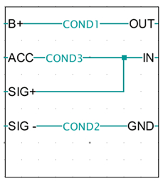
Figure 1: Simple ECU models suffice for fusing.
2. Current flow through electronic control units (ECUs):
Customers often tell us that the inside of ECUs is proprietary, and the task to model them is very daunting. When you focus on the task at hand -- determine if your fuses protect your wires -- modeling of the internal ECU connectivity is trivial with the right engineering tools. An example of all that might be needed is shown in Figure 1 (hypothetical example).
3. A model of the architecture of the vehicle describing the location of the components and the relative temperatures of each area of the vehicle and the harness interconnect points, as shown in Figure 2.
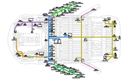
Figure 2: The vehicle architecture with component locations and temperatures.
4. Accurate models for the battery, fuses, wires, and the basic discrete devices found in your vehicle.
YOU CAN DO THIS
With the correct automation tools, a full analysis can be quickly run, as shown in Figure 3. Designers can take the recommended wire size (in the column Wire CSA (max)) and actually apply that to the design, driving part-number selection from this information.
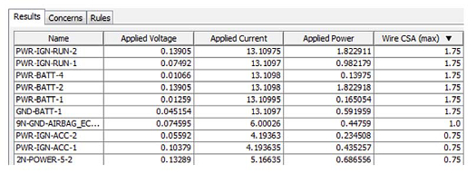
Figure 3: Automation allows engineers to apply standardized wire sizes directly to the design.
With this information, design decisions can be made early in the process, prior to any physical parts being built. By embedding the years of experience your engineers have, you can offer this level of analysis and decision-making to a much broader audience as well.
FINDING PROBLEMS EARLY SAVES MONEY
The later the problem is found, the more costly it is. Warranty and recalls cost vehicle manufacturers billions of dollars a year -- which significantly impacts the bottom line of companies that don't discover problems until the vehicles are already in customer hands. Where you want to find problems is as early in the design process as possible.
Enabling your design engineers to continuously analyze their designs prior to manufacturing a prototype saves time, money, and can improve reliability of your products. Most testing for electrical design starts in the prototype phase where the cost is highest. If you spend more time and energy up front, you will spend much less time, money, and effort during integration and have fewer warranty issues.
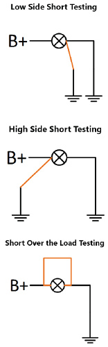
Figure 4: The three types of short-circuit testing used for wires.
REMOVING THE NEED FOR PROTOTYPES
A new method of sizing fuses with short-circuit testing is becoming popular, especially in Asia. The test includes three types of short-circuit tests, shown in Figure 4.
Typically, this type of analysis happens with physical testing. This entails building a very expensive prototype vehicle after the design is complete, which can cost upwards of $1,000,000 or more. These prototype vehicles are built not only for electrical testing but also physical testing. Short testing of this nature runs the risk of damaging the wiring, which would require an expensive repair in order to make the vehicle ready for the next test the vehicle is scheduled for. This type of testing should be accomplished in a virtual environment prior to design completion, prior to the building of expensive prototypes, and should be available to every harness engineer in your organization -- not in the hands of a select few simulation experts.
FUSES AND SMOKING WIRES
In Japan, they are using a method to size fuses such that under short-circuit testing the fuse will blow prior to the wire covering material beginning to fume, or smoke. Wire manufacturers in Japan are starting to publish the fume characteristics of wires so vehicle manufacturers and harness manufacturers can do this type of fuse sizing and wire sizing.
The idea is that if the fuse blows before the insulation material is compromised, the wire will last longer. When the wire heats up under stressful load conditions and the covering of the wire begins to fume, the durability of the wire is compromised. As the insulation in a wire deteriorates, it can potentially lead to a dangerous short. What if an airbag circuit shorting happened unexpectedly and the bag deployed while driving? Warranty and recall costs are staggering. The more testing you can do up front, the more design engineers you can have doing the testing, the easier the testing is and the better the products will be.
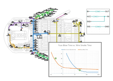
This type of testing, sometimes referred to as "Wire Smoke Testing," is being done with physical vehicle prototypes and is costly and time consuming. The principal of this type of testing is outlined below. Briefly, the load is shorted (either on the high side, low side, or across the load) and the circuit is observed. If the covering material of the wire begins to fume prior to the fuse blowing, then a solution is investigated. This could involve changing the fuse to a larger size, a fuse with a shorter blow time, a larger wire, a wire with a different material, etc. Figure 5 illustrates the concept.
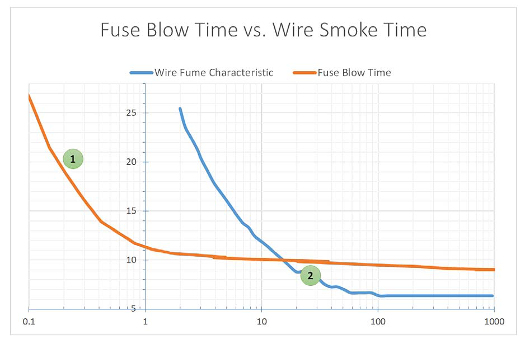
Figure 5: Fuse blow time and wire smoke time.
The graph in Figure 5 shows a hypothetical fuse and wire. The orange line is the Fuse Blow Time and blue line is the Wire Smoke Time (both in seconds) vs. Current (amps).
Two points on the graph are of special interest. At about 20 amps, with this wire and fuse combination, the fuse will blow (orange line) prior to the wire smoking (blue line). This is the desired condition. Also, at about 8 amps, we see the wire will smoke prior to the fuse blowing. This is NOT the desired condition, as it could lead to deterioration of the wire material and cause a durability issue overall.
Software tools are now capable of much of this testing. They include:
- Full vehicle load testing;
- Automated testing of multiple vehicle configurations;
- Automatic Fuse sizing and part number selection;
- Automatic wire sizing and part number selection;
- Automated short-circuit testing -- High side, low side, over the load or rotating through all three; and
- Testing for fuse blow time vs. wire material fume time to increase the durability of your wiring
SUMMARY
Testing physical prototypes presents two expensive problems: (1) the prototype is very expensive to build and maintain, and (2) faults found as late as the prototype are very expensive to fix. The solution is to employ virtual prototypes and simulation for systems that can be properly simulated. Wiring harnesses are readily simulated, and virtual prototypes can readily detect faults, such as short circuits or time for the fuse to blow vs. time for the wire to smoke. Employing these tools can not only save a great deal in costs, but can remove significant time from the development cycle as well.
Learn more about Mentor Graphics solutions for electrical and wire harness design -- like its Capital Design Tools -- here.
Published April 2016
Rate this article
View our terms of use and privacy policy